Dog Carrier Backpack Hardware: Zinc Alloy vs Iron
For dog carrier backpack hardware, compare zinc alloy and iron across 4 controls: substrate grade, geometry, finish system, and installed proof-load performance. Zinc alloy is usually preferred for shaped, branded components, while iron or steel is often selected for thin stamped rings, adjusters, and cost-controlled load parts. Neither material is automatically stronger or more corrosion resistant. Specify alloy or steel grade, geometry, section thickness, finish, rated working load, proof test, and salt or moisture exposure before approving a buckle, hook, D-ring, or adjuster.
Executive Summary
Hardware selection should begin with the complete load path and contact environment. Zinc alloys support die-cast three-dimensional forms, logos, and consistent decorative surfaces but can fracture if sections, radii, alloy, or porosity are poorly controlled. “Iron” hardware is normally a commercial description for stamped, bent, or welded ferrous components; the exact steel and heat or surface treatment still need definition. Ferrous parts can provide efficient strength in thin sections but rely heavily on plating, coating, weld quality, and edge finishing for corrosion and contact safety. The program baseline is MOQ 500 pieces per color, samples in 6-10 working days, bulk production in 35-50 days, and final workmanship sampling to AQL 2.5. Qualify each component through dimensional checks, visual standards, proof loading, deformation or fracture criteria, cycling, attachment testing, and environmental exposure. Include substrate, manufacturing process, finish stack, color master, mating webbing size, and approved source in the BOM. The best hardware is not the heaviest component; it is the lightest traceable design that maintains geometry, retention, finish, and safe edges throughout the specified carrier load and service sequence. Bulk release should record substrate, finish batch, cavity or tool identity, incoming checks, and installed proof-test evidence for every safety-critical part.
The difference between one dog carrier factory and another is rarely the stitch count - it is whether the dog carrier backpack pattern survives a 1.5x static load without permanent set.
Clarify the Material Terms Before Comparing Hardware
“Zinc alloy” commonly describes a family of die-casting alloys, not one guaranteed chemistry or strength level. Alloy composition, casting process, porosity, wall thickness, draft, fillets, and post-finishing all influence performance. A sample with a smooth plated surface can hide voids or cold shuts that reduce load capacity. The drawing and purchase specification should identify the agreed material grade or composition standard, manufacturing route, dimensions, finish, and mechanical acceptance.
“Iron” is even less precise in bag-component trade language. Many wire rings, stamped adjusters, hooks, and buckles described as iron are produced from low-carbon steel strip, sheet, or wire. Steel grade, thickness, wire diameter, temper, weld process, forming radius, and finish matter. Cast iron is generally not the intended material for these small formed carrier parts, so technical documents should replace the casual term with the verified ferrous substrate.
Compare equivalent functions and sizes. A thick die-cast zinc snap hook and a thin formed steel hook may have different geometry, gate opening, rotation, weight, and failure mode. A decorative zinc adjuster may not grip webbing like a stamped steel tri-glide. The carrier engineer should define the required interface first: webbing width and thickness, movement, opening clearance, retention, edge radius, contact direction, and load.
Finish names such as gunmetal, nickel, matte black, or antique brass describe appearance, not substrate or coating performance. Record the finish stack, target color or gloss, coating thickness where relevant, corrosion target, and restricted-substance requirement. Keep labeled physical masters under controlled storage.
A valid zinc alloy versus iron comparison begins only after substrate, forming process, geometry, finish system, and test condition are made explicit. This prevents procurement from treating visually similar parts as interchangeable when their structural and environmental behavior is not equivalent. It also gives incoming inspectors concrete identification points and prevents a finish-color match from overriding the approved engineering basis.
Map Each Component Into the Carrier Load Path
Hardware should be classified by consequence of failure. A decorative badge has different risk from a shoulder-strap adjuster, carry-handle ring, tether hook, or convertible-mode attachment. Mark every load-bearing component on the structure diagram and trace force into webbing, reinforcement, shell, and base. The hardware rating must be considered with the weakest adjacent element; an extremely strong ring adds little if the webbing seam pulls from the panel.
Define working load and proof load separately. Working load is the allowable service condition set by the product design. Proof loading checks a higher controlled level without unacceptable deformation, release, cracking, or loss of function. Ultimate testing can identify failure margin and mode but may destroy the component. Safety factors and loads should reflect dynamic movement, orientation, and multiple carry modes rather than simply matching dog mass.
Geometry directs stress. Sharp internal corners in die-cast zinc concentrate strain, while generous radii and uniform sections reduce local peaks. Thin cast walls around pin holes or gates require particular attention. Stamped steel can crack at tight bends or develop burrs and may open if a ring gap or weld is weak. Wire diameter, weld penetration, and forming springback control D-ring behavior.
Load the component in the direction it experiences in the bag. A snap hook pulled straight may perform differently when side-loaded or twisted by a strap. An adjuster must grip the nominated webbing without cutting it or slipping during cycles. A swivel should rotate under representative tension without unscrewing, binding, or exposing sharp interfaces.
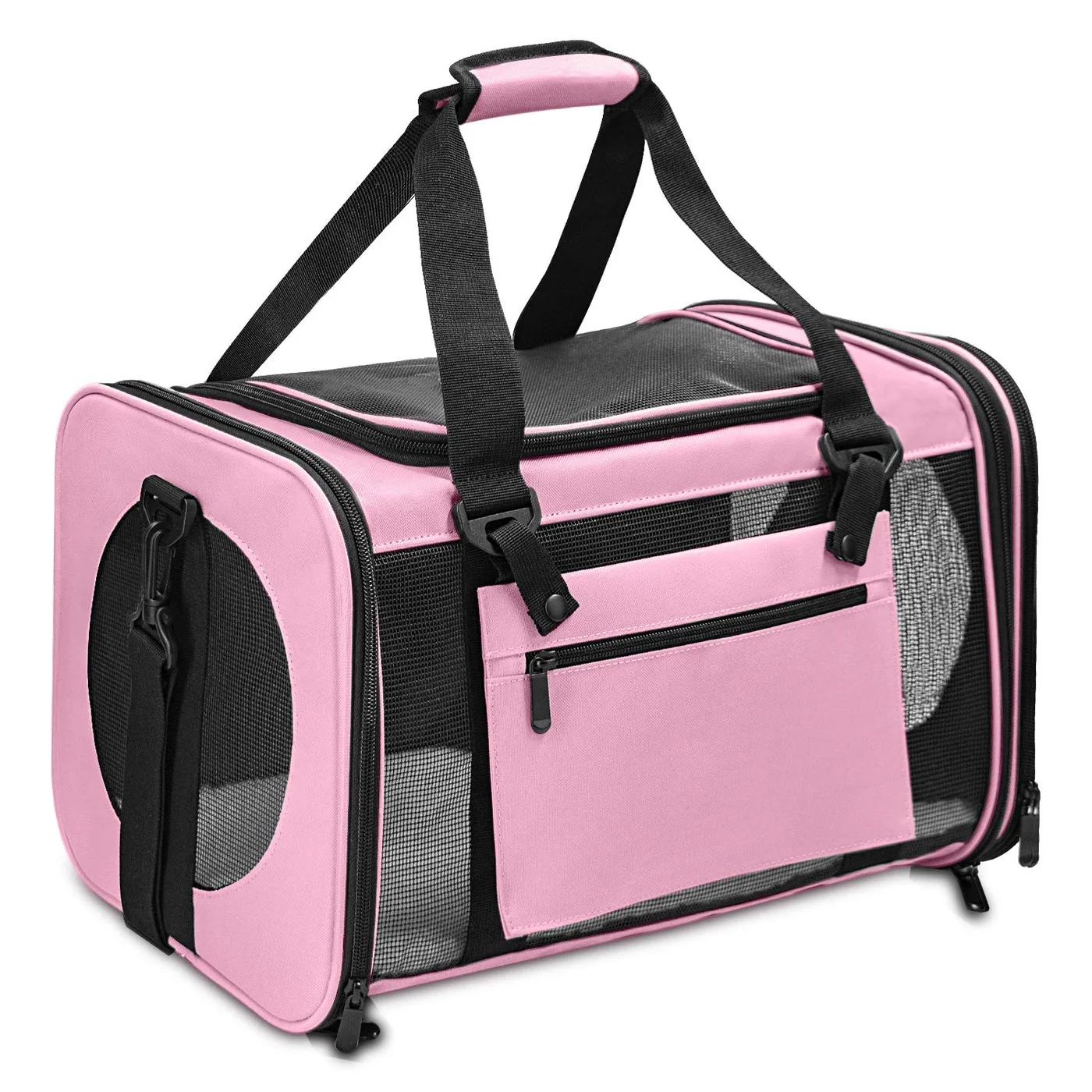
Hardware capacity for a dog carrier backpack must be established on the installed assembly and in the actual force direction, not inferred from component mass or material name. Document component proof results and complete-anchor results so design changes in webbing or sewing trigger the correct retest.
Compare Strength, Deformation, Weight, and Failure Mode
Die-cast zinc hardware often provides dimensional detail and stiffness, but overload may produce limited visible yielding before fracture depending on alloy and geometry. Porosity can create variation between parts. Formed steel components may bend or open before breaking, although thin sections, weld defects, or embrittlement can cause abrupt failure. Neither generalized description replaces testing of the exact component batch.
Weight matters because several hooks, rings, adjusters, feet, and pullers accumulate. Added hardware mass increases the empty carrier weight and can swing or strike panels during walking. Place hardware where it does not create a hard pressure point against the animal or wearer. A larger part may improve hand access but also require thicker reinforcement and more packaging clearance.
Dimensional stability affects mating. Buckle tongues, pin holes, gates, swivels, and webbing slots need tolerances that permit movement without excessive play. Die wear, casting shrinkage, plating buildup, stamping springback, and coating thickness can move these dimensions. Use functional gauges for critical interfaces, especially when halves come from different tools or sources.
Failure criteria should distinguish cosmetic change from unsafe function. Small finish wear may be acceptable after cycling, while a crack, gate release, ring opening, pin migration, webbing slip, sharp burr, or permanent deformation beyond limit is not. Record force-displacement behavior when possible because a part that remains attached but stretches enough to release webbing has failed its function.
The preferred substrate is the one whose validated failure margin, deformation behavior, mass, and mating tolerances suit the specific carrier location. Use separate requirements for main load hardware, adjustment hardware, tether components, zipper pullers, and decoration rather than applying one blanket material rule.
Variation must be included in the comparison. Test parts from multiple casting cavities, stamping tool positions, wire coils, and finish batches when those sources can be identified. Measure section thickness, slot width, pin diameter, gate opening, and mass to detect process spread before destructive loading. Plot individual proof and ultimate results by cavity or lot instead of pooling all values immediately. A low cluster may indicate local porosity, tool wear, weld setup, or material variation. Engineering approval should use the lower observed capability with a suitable margin, not the single strongest sample. This statistical view is especially important for brittle failure modes that provide little warning in use. The resulting limits should be recorded on both the drawing and inspection plan. The record supports release.
Engineer Plating and Coating for Corrosion Resistance
Zinc alloy and ferrous hardware both depend on surface preparation and finishing. Die-cast parts may be polished, plated, painted, electrophoretically coated, or otherwise finished. Steel can be zinc plated, nickel plated, painted, powder coated, or treated with another specified system. Adhesion and corrosion behavior depend on cleaning, activation, underlayers, thickness, curing, and geometry. Recesses and contact points often receive different coverage than broad visible faces.
Corrosion testing must state exposure method, duration, orientation, evaluation interval, and acceptance. Salt spray can compare controlled finish systems but does not directly predict every real service life. Humidity, perspiration, rainwater, cleaning chemicals, and contact with dyed or coated textiles create different mechanisms. Select exposures based on intended use and evaluate red rust, white corrosion products, blistering, peeling, discoloration, staining, and continued operation.
Moving interfaces wear coatings. Cycle snap-hook gates, swivels, adjusters, and buckles before and after environmental exposure. Inspect pivots, slot edges, corners, welds, and contact bands because these reveal substrate first. A decorative finish that passes on an untouched plaque may fail rapidly on a working adjuster. Use the actual mating webbing to evaluate abrasion and color transfer.
Packaging can produce its own micro-environment. Hardware touching damp textile or trapped against coated fabric can stain or imprint during humid transit. Pack conditioned samples using the production method, expose them to the agreed temperature and humidity profile, and inspect after recovery. Protective films should not leave adhesive or create small loose pieces.
A hardware finish is qualified only when the complete component preserves safe edges, acceptable appearance, and intended movement after both wear and environmental exposure. Keep substrate and finish records linked; changing the base metal while retaining the same color name requires a new review.
Design Cast, Stamped, Bent, and Welded Details for Production
Die-cast zinc geometry needs uniform walls, smooth transitions, suitable draft, accessible gates, and controlled ejector locations. Thick-to-thin transitions can feed poorly and create shrinkage or voids. Cosmetic faces should identify allowed parting lines, gate vestige, sink, flow marks, and polishing limits. Logos need minimum stroke and relief suited to the process. Critical pin bores and webbing slots may require secondary sizing or gauging after plating.
Stamped steel uses sheet thickness, blanking clearance, bend radii, forming sequence, and tool condition to control shape. Burr direction should face away from webbing and contact surfaces, or edges must be tumbled and finished. Tight slots can cut webbing; wide slots can permit twisting. For wire rings, define diameter, inside dimensions, gap, weld location, penetration or closure requirement, and roundness.
Welds deserve specific acceptance. A polished surface can conceal incomplete fusion, while excessive grinding can reduce section. Establish visual criteria, dimensions, proof tests, and destructive checks at a risk-based frequency. If plating follows welding, confirm that cleaning and finish reach the joint without trapping residues. Heat-affected zones can change appearance and strength.
Mold and tooling approval should use dimensioned first articles from each cavity. Identify cavity marks where feasible so repeated defects can be traced. Measure high-risk dimensions before and after finishing, since coating buildup can close slots or alter mating. Store approved master parts by revision and finish.
Manufacturing process belongs in the hardware specification because casting, stamping, bending, welding, and finishing create different defects even when final outlines look alike. Process-specific controls reduce the chance that cosmetic sorting overlooks structural variation.
Build a process-control plan around characteristics that create load performance. For die casting, monitor alloy identity, melt and die parameters, cavity condition, gate trimming, and porosity indicators appropriate to the part. For stamping and wire forming, control incoming thickness or diameter, tool wear, bend dimensions, gap, and burr direction. For welding, lock machine settings, electrode or fixture condition, joint location, and verification frequency. First-off and last-off samples help reveal drift across a production run. Any rework such as welding, grinding, straightening, or replating needs a defined limit and record because it can change section, heat history, or coating integrity. Uncontrolled cosmetic repair should never be used to conceal a structural defect.
Build a Hardware Test Matrix and Acceptance Table
The test plan links each component function to an installed condition. Use calibrated fixtures that do not introduce unrealistic edge loads, and document loading rate, direction, duration, cycles, sample quantity, conditioning, and failure definition. Test incoming components where useful, but always verify safety-critical parts after attachment to the actual webbing and carrier structure.
| Hardware feature | Primary verification | Typical failure to record |
|---|---|---|
| D-ring or rectangular ring | Proof load in installed orientation | Opening, weld crack, permanent distortion |
| Snap hook | Body load, gate cycling, side-load review | Gate release, fracture, swivel bind |
| Webbing adjuster | Slip and cycling with nominated webbing | Strap creep, edge cutting, deformation |
| Buckle | Mating, release force, proof and cycle tests | Unintended release, latch wear, crack |
| Rivet or stud | Installed pull and rotation check | Pull-out, sharp back, cap separation |
| Finish system | Wear plus environmental exposure | Rust, blister, peel, stain, unsafe edge |
Reference test-method resources can be searched through ASTM International. Quality record control can follow principles summarized by the ISO 9001 quality management page. These references do not set a universal dog carrier load; the buyer and engineer must define the exact model requirement and acceptance margin.
Record individual results and failure locations, not only an average. A single brittle fracture may be safety-significant even if mean force is high. Retain failed samples and untested controls by lot. A hardware test matrix is complete when every load-bearing or detachable part has a reproducible installed test and a clear release, containment, or rejection action.
Fixtures and instruments require their own control. Verify calibration status, jaw alignment, loading axis, grip protection, travel measurement, and data-acquisition rate before the series begins. A hard metal jaw can nick webbing and create a false anchor failure; an off-axis fixture can side-load a snap hook that is intended for straight pull. Photograph each setup with dimensions and record the installed orientation. Repeat tests after environmental exposure using the same fixture and loading rate. Where release force or strap slip is measured, mark the starting position and define allowable movement. These controls let results from zinc and ferrous alternatives be compared without test-equipment variation dominating the conclusion.
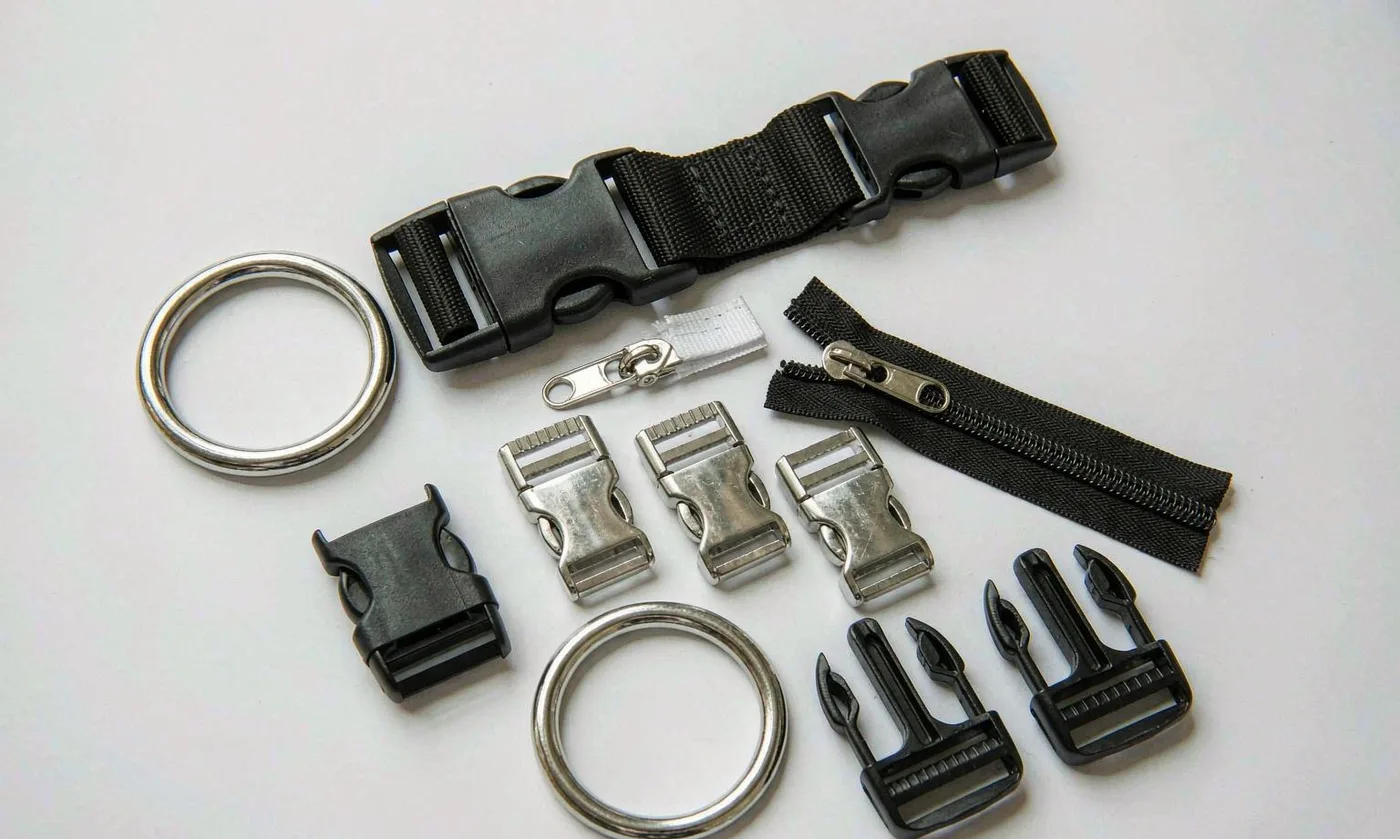
Control Chemical Compliance and Contact Safety
Metal substrate, plating, conversion coatings, paints, clear coats, lubricants, solder, and plastic inserts can all contribute regulated substances. The applicable limits depend on market, product classification, buyer policy, and contact scenario. European regulatory research can start at ECHA, while California chemical information is available from OEHHA. The compliance file must identify the exact part, finish, color, source, test scope, and date.
Do not treat one plating certificate as coverage for every finish. Black, nickel, antique, painted, and clear-coated variants can use different process chemistry. A substrate change can also affect pretreatment. Create a finish family matrix and define which variants require separate reports or risk assessment. Revalidate after source, chemistry, process, or regulatory changes.
Contact safety includes geometry. Inspect edges, gate vestiges, burrs, weld flash, rivet backs, pinch gaps, and fracture behavior. Use tactile and dimensional criteria, then repeat inspection after cycling and corrosion exposure. A smooth new component can develop rough plated edges as wear exposes layers. Hardware facing the dog compartment should be shielded or positioned to avoid concentrated contact.
Small detachable parts require attachment tests and an assessment of foreseeable chewing or manipulation. Tether hooks and internal rings should not create entanglement geometry. Decorative pieces should not be mounted where a failure releases fragments into the compartment. State whether a component is structural, functional, or decorative so inspectors understand its defect severity.
Compliance evidence is credible only when it traces to the exact substrate-and-finish combination installed on the approved carrier revision. Keep declarations, test reports, risk assessments, and change notices with the BOM rather than in a generic supplier folder.
Plan laboratory samples before placing the hardware order. The submission sheet should show component photograph, code, substrate, finish stack, color, supplier, intended carrier location, and requested analytical scope. Send enough parts from a traceable production-intent lot and retain controls. Review the report for model identification, preparation, method, detection limit, result, and laboratory details rather than accepting a pass summary. If several components share a finish bath, document the technical basis for grouping; different substrates or paints may still require separate coverage. Link the accepted report to purchase and incoming records. When regulations or buyer limits change, screen the active BOM and prioritize high-contact, plated, painted, soldered, or flexible coated parts for renewed assessment.
Approve Hardware for Sampling, Bulk Production, and AQL
Sample development should compare complete hardware sets on the actual carrier. Within the 6-10 working day sample cycle, check mating, webbing fit, hand access, noise, contact, mass, opening clearance, and initial finish. Build load coupons for critical anchors, then verify the finished prototype under proof and cycling conditions. The pre-production sample should use approved substrate, geometry, finish, and source with every deviation listed.
At MOQ 500 pieces per color, custom die-cast logos and plated colors may have component minimums greater than the bag order. Confirm tooling ownership, cavity count, first-article approval, color masters, spare allowance, and lead time before bulk release. Tooling and finish development can sit on the schedule critical path. The 35-50 day production plan should include incoming hardware inspection before dependent subassemblies start.
Incoming inspection verifies packaging identity, lot, dimensions, mass where useful, mating, gate or latch function, edges, finish, and sampled proof or other tests according to risk. Inspect parts from multiple cartons and cavities. Segregate finish lots to avoid visible mismatch. Quarantine any unapproved substrate or source substitution even when the color appears correct.
In-line quality checks that hardware orientation, webbing routing, seam capture, rivet setting, keeper placement, and protective backing match the operation sheet. Final AQL 2.5 inspection samples function, workmanship, dimensions, labels, and packing, but qualification records remain necessary for load and corrosion performance. Trace finished cartons to component lots and current revision.
Bulk hardware release requires consistent first articles, controlled incoming lots, verified installed strength, stable finish, and an approved change path. This system lets either zinc alloy or ferrous hardware be selected on evidence rather than assumption while protecting load safety and appearance through shipment.
Create a written reaction plan for receiving and in-line failures. If dimensions, finish, function, or sampled proof results miss the limit, identify affected lots, stop issue to production, and segregate components physically and in records. Review whether units already assembled require 100 percent checks, sampled destructive testing, rework, or rejection. Supplier replacement is not complete until the new lot passes the original identity and performance controls. Trend defects by cavity, finish batch, carton, and assembly station to separate source problems from rivet setting, webbing routing, or sewing errors. Close the nonconformance with evidence, then update risk and inspection frequency. This prevents schedule pressure from converting a contained component problem into an expensive finished-carrier recall.
Production capability
- SGS-verified production space of 4,950 m², 149 machines, 7 assembly lines
- Pet carrier and pet bag output since 2014 from a 137-person team
- 200,000 units shipped monthly under BSCI and ISO 9001 systems
People Also Ask
Is zinc alloy stronger than iron hardware?
Not universally. Strength depends on exact alloy or steel grade, geometry, process, defects, finish, load direction, and installed test results.
Why use zinc alloy hardware on a dog carrier backpack?
Zinc alloy supports detailed die-cast shapes, branding, and decorative finishes when wall design, porosity, and proof performance are controlled.
Why use steel or iron hardware?
Formed ferrous parts can provide efficient strength in thin rings and adjusters, but edges, welds, plating, and corrosion need control.
Does metal hardware need a salt spray test?
Use salt or other environmental exposure when it reflects the specification; state method, duration, evaluation, and post-exposure function.
How is hardware load capacity tested?
Apply a defined proof or ultimate load in the installed direction using the actual mating webbing and attachment structure.
Can decorative finish color prove the substrate?
No. Similar nickel, gunmetal, black, or brass appearances can cover different substrates and coating systems.
Frequently Asked Questions
What zinc alloy grade should be specified?
Use the verified grade agreed with the component source and document chemistry or standard, process, dimensions, and mechanical acceptance.
Is bag hardware really made from pure iron?
Usually the trade term refers to low-carbon steel sheet, strip, or wire; technical documents should identify the actual substrate.
What is a proof load?
It is a defined load above normal working conditions that the component or installed assembly must withstand without prohibited damage or deformation.
Why test hardware after plating?
Finishing can change dimensions, conceal defects, affect embrittlement risk, and alter corrosion, mating, or moving-interface behavior.
How are sharp edges controlled?
Specify edge radii and burr limits, inspect after forming and finishing, and repeat checks after cycling and environmental exposure.
Can hardware weight affect carrier design?
Yes. Multiple parts add empty mass, swing during movement, influence balance, and may require packaging clearance or protective layers.
What should a metal finish master show?
It should identify approved color, gloss, texture, acceptable variation, substrate, finish process, date, and revision.
How are welded rings inspected?
Use visual and dimensional criteria, sampled proof tests, and risk-based destructive section checks for fusion and reduced section.
Does AQL 2.5 replace proof testing?
No. AQL samples lot conformity; proof and environmental qualification use separately defined specimens, frequencies, and limits.
When must hardware be requalified?
Review changes to substrate, geometry, thickness, tool, cavity, weld, source, plating chemistry, finish, or mating material.
Can zinc and steel parts share one finish color?
They can be color matched, but different pretreatments and coating stacks require separate approval and may age differently.
How is hardware traced in bulk orders?
Link supplier lot or batch records through receiving, subassembly, inspection, and finished-carton production records.
Talk to QUANZHOU JUNYUAN BAGS about a pet carrier program: MOQ 500 pieces per colourway, samples in 6-10 working days, bulk production in 35-50 days under AQL 2.5 inspection.
Get a free quote Request a sample